Visitor 3 Manual
Introduction
This manual will explain the basic functions of Visitor3, the terrain and landscape editing tool for Armed Assault.
Version 3 of Visitor has improved features over its predecessors:
- Easier object handling
- All operations are much faster (especially with large number of objects)
- Support for surface materials rvmat and new transition materials bimpas
- Import/Save landscape profiles from/to images (.png format)
- Completely in English
- Improved road networks creation
- Script support (.vis)
- Background overlay images
- Source control integration
- Reworked and polished UI allowing docking of toolbars etc.
Installation and Setup
Interface
Most of the buttons are selfexplaining, so only the important ones should be explained. If you used old visitor you will notice that the buttons for selections and object handling disappeared, since this is now done over a combination of shift/Ctrl and mousebuttons.
Most important in first line of tool buttons are (To start Buldozer) and
(To align the map to window).
contains additional filters and view options.
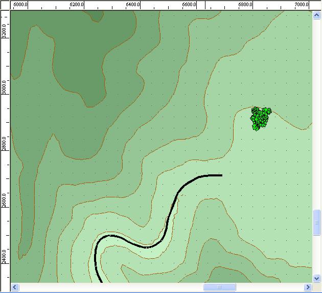
The actual view is shown in the mapwindow:
The current editormode is shown in this window:
MMB points cursor on new location.
RMB is used for sliding over map.
LMB deselects/selects/places objects/surfaces.
For selecting areas press and hold the left mousebutton (LMB) and move it over the area.
For additional areas to the already selected one, press CTRL+LMB.
For excluding areas use SHIFT+LMB.
For selecting an object on map, click on it with the LMB.
To select several objects drag a selection box around them or use CTRL+LMB to add them to selection.
To rotate one or several selected object/s, hold CTRL (or SHIFT), click on them an move your mouse up or down.
How to Make Your First Map
- Create new project ( Project -> New , Ctrl + N )
- Select wanted size (e.g. width 2000 m, square size 50 m)
- Set project preferences ( Tools -> Project preferences... ), fill in basicmap\data to Folder - Textures field
- Create surface texture gr.tga in p:\basicmap\data (texture file name is recommended to be only two letters to allow easy transition generation).
- Create surface from Tools -> Textures... , first define new terrain type (New... button, name it basic), add texture to it (Add button, use basic as the Surface name, click on Select and open gr.tga )
- Select entire map area (Edit -> Select All , Ctrl + A)
- To change height of the map, switch to Landscape Vertexes editing mode (F9) and select "Change height...", in the dialog Change height select Height option and fill in Height field desired value (e.g. 100 m above sealevel)
- To put texture on the map, switch to Landscape textures mode (F1) and click on "Set texture onto area".
- Open realtime viewer (Project -> Connect to buldozer, Ctrl + F7)
- To export your map for the engine, select Project -> Export world... , and store it to basicmap\basicmap.wrp , realtime viewer has to be running.
Tools
Textures
This method is no longer used. See this article instead.
Natural Objects
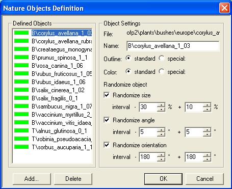
All flowers,bushes and trees used on the map will be defined here.
- "Add": Add an object, browse the opening list to select the model you want to use. Note that you have here a maximum length for a name of 50 characters.
- Randomize Size Interval: Model size will be randomly set in the given interval when placed in Visitor.
- Randomize Angle Interval: Model angle will be randomly set in the given interval when placed in Visitor.
- Randomize Orientation Interval: Model facing direction will be randomly set in the given interval when placed in Visitor.
Artificial Objects
Structures definitions.
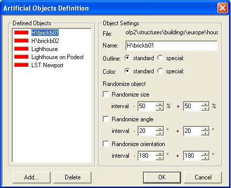
All artificial objects, like buildings, walls or street signs are defined here.
Same as in Natural Objects.
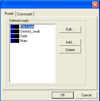
Roads
Road types and sections definitions go in here.
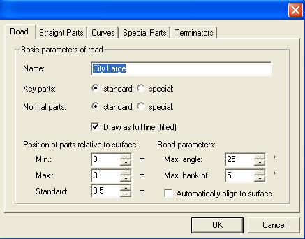
After hitting "Add" or "Edit" the Main setting window for the road shows up.
- Road: Main settings for given road type.
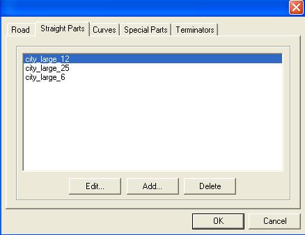
- Straight Parts: all straight sections of this road type.
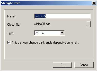
Note that those parts need a certain length: 6.25, 12.5 or 25 meters.
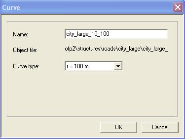
- Curves: all curved section of this road type.
Note that those parts need a certain radius: 25, 50, 75 or 100 meters.
- Special Parts: Sections with special appearance like a T-shape. Same way defined as straight parts.
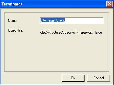
- Terminators: Sections that ends a road.
Forests
Todo. Forest definitions. Generally, forests are obsolete concept and shall be replaced by individual trees or more universal solution for placing object.
Project Preferences
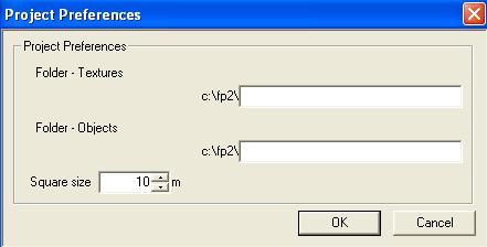
Paths to textures and objects (if stored in a specific place) and other project specific settings.
- Folder - Textures: Path to the folder where all landscape textures are stored.
Note that the path is saved relative in the map, so you have to maintain folder structure.
- Folder - Objects: Path to the folder where all objects used in Vistor are stored. This path is also relative saved.
- Square Size: Ingame side length of one square in visitor.
Object Manager
TO DO!!
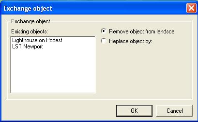
Replace Objects
Deletes or replaces all instances of an object (models) from the map.
Random Object Placer
Places objects in a random pattern to an area. The settings for random placing can be defined and will be stored in configuration profiles for later further use. Can be used for light forests.
- Template: Object used, the object is either defined under Natural Objects or Artificial Objects.
- Density: Density of that Object per square.
- Collision free: Defines if the object needs to be placed collision free (like in example for buildings or trees).
Snap Objects
Closes small gaps that can occur when placing objects like fences, walls. Note that objects need to be prepared for snapping.
Editing Modes [F1-F10]
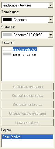
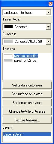
Landscape - Textures [F1]
Sets textures/properties to surfaces.
- Terrain type: Current selected terrain type.
- Surfaces: Current selected surface.
- Textures: Current selected texture, if set to "random selection" it will randomly choose on of the available textures.
- Set Texture Onto Area: Set current texture on selected area.
- Set Surface Onto Area: Set current surface on selected area. The textures are set according to their probabilities.
- Set Terrain Onto Area: Set current terrain on selected area. The surfaces are set according to their definition. Same for the textures.
- Change Texture Onto Area: Changes texture in area to current selected texture.
- Texture Analysis..:
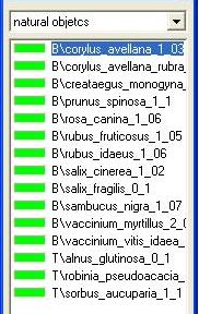
Natural Objects [F2]
Placing all natural objects, except forests.
List of all natural objects. Select an object and click on the map where you want to place it.
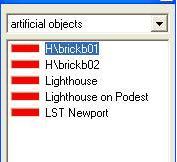
Artificial Objects [F3]
Placing all artificial objects (houses and other structures), except roads.
List of all artificial objects. Select an object and click on the map where you want to place it.
Woods [F4]
Creating forests.
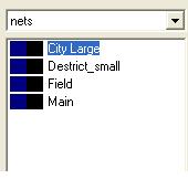
Nets [F5]
Placing roads.
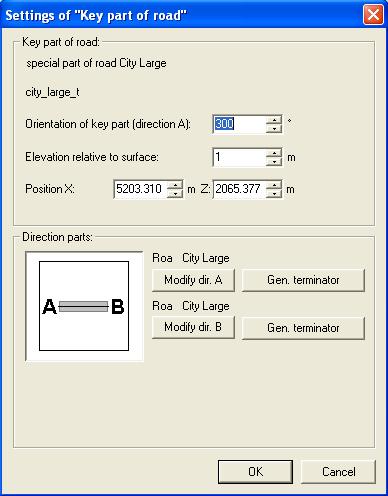
List of all road types. Select a type and click on the map where you want to place it. A dialog will pop up leading you through the placement process. Note: You only have to place the first key part of a road section. Then you can simply click on the map and Visitor will try to reach the point, autoplacing the road. In case you don't like the placement you can change it manually, which is a bit more time consuming. If you click on a placed road, the road property window will show up.
Every road part (except terminators) have two main directions: A and B, reflecting both ends of that key section. Visitor uses the closest end of a road to reach a point clicked on the map.
- Orientation Of Key Part (Direction A): Direction the A end is facing, angles are only possible in 10° steps.
- Position X and Position Z: Position of the key part on the map.
- Gen.Terminator: Creates Terminator or new Key section at the end of that direction
- Modify Dir. A:
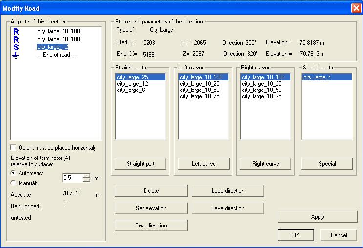
Note: -Deleting/Adding a part in the middle of the road changes also the rest of the road. -Added sections will be inserted before the section marked in "All Parts Of This Direction".
- All Parts Of This Direction: All sections from the key section to the end of the road
- Delete: Delete selected section.
- Straight Part: Adds the selected straight part to the road.
- Left Curve: Adds the selected left curve section to the road.
- Right Curve: Adds the selected right curve section to the road.
- Special: Adds the selected special section to the road.
Named Zones [F6]
Display/Create named zones.
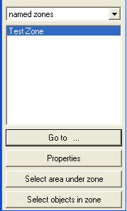
List of all named zones on the map.
To name a zone click LMB on map screen the selection box.
- Go To...: Centres the view on selected zone.
- Properties: Opens properties window (same as double clicking the selection).
- Select Objects In Zone: Selects all objects that are in this zone.
- Select area under zone:
...
Key Points [F7]
Display/Create key points.
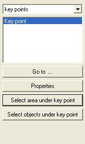
List of all key points on the map. To add key points, click LMB on the map in this editing mode.
Same options as in [[#Named Zones [F6]]] editing mode.
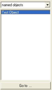
Named Objects [F8]
Browser for all named objects on the map.
Landscape Vertexes [F9]
Landscape height changing. Landscape forming tool.
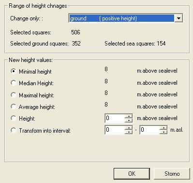
Change Height: Changes the height of points/area on the map.
- Change only: Shows only up when the selection has sea and land points.
Ground (Positive Height): Only points over sea level will be changed.
Sea (Negative Height): Only points below sea level will be changed.
- Minimal Height: All points will set to the height of the lowest point of selection.
- Median Height: All points will set to the median height of selection.
- Maximal Height: All points will set to the height of the highest point of selection.
- Average Height: All points will set to the average height of selection.
- Height: All points will set to this height.
- Transform Into Interval: Takes the current height profile of selection and stretches it into the given interval.
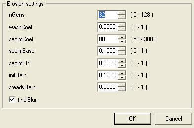
Erosion: Erodes Landscape.
- nGens: Number of generations of erosion (max. 128 generations).
- WashCoef: Wash Coefficient, how strong does water flow affect terrain.
- SedimCoef: Sediment Coefficient, how fast sediments sink down and stay where they are.
- SedimBase: Sediment Base, how much sediment is there from the beginning.
- SedimEff: Sediment Effect, "wash out" resistance of terrain.
- Initrain: Strength of rain.
- SteadyRain: How long does the rain last.
- FinalBlur: Creates a smoother surface.
Background Image [F10]
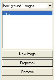
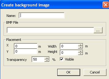
Sets a backgroundpicture as reference. Only bmp files are supported.
To see the background image, in the "Create background image" dialogue (below), first choose some BMP file. Placement values are coordinates for top left corner (for the image covering whole map, set both to 0). Width and Height are true sizes of imported image. Example: If the map is e.g. 10240x10240 meters and the background image covers whole area, set Width and Height values to 10240. Smaller hi-res images can be used as well, if the coordinates and size are set correctly.
Terrain
You have several options to edit the height profile of your map:
- Manually ("Landscape - Vertexes" as editor mode/F9): This is the most work intensive version, you change all landscape point individually. We recommend to use this method only for fine tune a map.
- Import ASE Height Map (Projects/Import Terrain): Read in an 3D Studio Max .ase height map. This will be more likely removed in future.
- Import PNG Image (Projects/Import from Picture): Imports 8 or 16 bit PNG image, a PBL config must be present (it's created automatically when you export PNG file in the same location). PBL file example:
class cfg
{
	PNGfilename="world.png";
	squareSize=5.000000;
	originX=0;
	originY=0;
	minHeight=120.000000;
	maxHeight=735.000000;
};
- Import from XYZ map (Projects/Open "Files of type: *.xyz"): XYZ is ASCI file format containing space delimited X Y Z on each line, where XY is UTM and Z is in meters. During import you can align data to top or bottom left and set target data dimension to crop data or extend area.
- Inside Buldozer: You can use U (small step up), I (big step up), J (small step down) and K (big step down). This is also best used for fine tune the profile.
Note: for import terrain operations (and any other large scale operations like this) it's recommended to disconnect buldozer otherwise it takes really long time to process the map.
Scripts
Visitor 3 gives you the opportunity to use scripts for certain tasks. Visitor script files have the extension .vis.

