Helicopter Flight Model Config (XML)
What is RotorLib FDM?
RotorLib FDM is RTDynamics' rotary wing aircraft flight dynamics model solution. It includes aerodynamic models, ground contact model, flight instrument models and flight control system simulation.
RotorLib FDM is designed for pilot-in-the-loop applications such as flight training simulators, mission rehearsal systems and combat training simulators.
RotorLib Flight Dynamics Model
GenHeli600 model
The generic RotorLib FDM helicopter flight dynamics model is implemented in RotorLibFDM::GenHeli600 class. This class uses several mathematical models as components to create a generic helicopter model. GenHeli600 consists of:
- rotor models
- vertical and horizontal stabilizers & wings
- fuselage model
- ground contacts (skids, wheels, inflatable buoys)
- engine model
- drive train model
- flight control system
- flight instruments
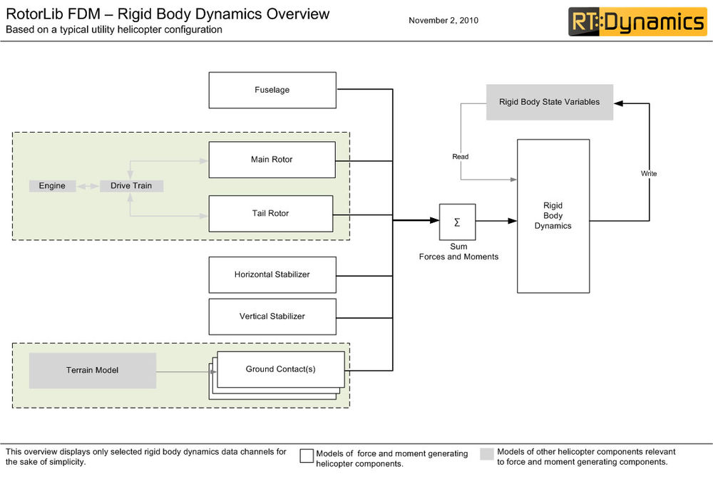
Forces and moments computed by these models are used by a real-time rigid body dynamics model to update the rigid body state of the helicopter. Below you can find an overview of the flight dynamics model.
GenHeli600 configuration
GenHeli600 flight dynamics model is configured through XML configuration files. These configuration files are given to the constructor of the GenHeli600 class.
Configuration files start with an FDM type declaration and file version definition. Configuration parameters are defined between the opening and closing tags of this type declaration. The simplified layout of the configuration is provided below.
<GenHeli600 version="1.0">
	<!-- Physical parameters of the Main Body -->
	<MomentsOfInertia Ixx Iyy Izz Iyz /><!-- Kg*m^2 -->
	<Mass mass /><!-- Kg -->
	<CenterOfGravity x y z /><!-- meters, relative to reference datum -->

	<Fuselage>
		<!-- GenHeli600 fuselage model is implemented using RotorLibFDM::FGHeliFuselage100 model. See Fuselage section below for details. -->
	</Fuselage>

	<Engines>
		<Engine type>
			<!-- Configuration for the chosen engine models must be provided inside the <Engine> </Engine> tags -->
		</Engine>
		.
		.
		.
		<Engine type>
			<!-- The number of engines that can be added to a helicopter is not limited. -->
		</Engine>
	</Engines>

	<DriveTrains>
		<DriveTrain type>
			<!-- Configuration for the chosen engine model must be provided inside the <DriveTrain> </DriveTrain> tags -->
		</DriveTrain>
		.
		.
		.
		<DriveTrain type>
			<!-- The number of drive trains that can be added to a helicopter is not limited. -->
		</DriveTrain>
	</DriveTrains>

	<ControlSystem>
		<CSComponent type >
			<!-- Flight control system configuration. In this section a multitude of flight control system components can be defined. -->
			<!-- Each component should be defined in a separate <CSComponent> section. -->
			<!-- type parameter in CSComponent defines which component type (e.g. FCSRotationDamper ) will be created. -->
		</CSComponent>
		.
		.
		.
		<CSComponent type >
			<!-- Inside the <CSComponent> </CSComponent> configuration parameters of the chosen component model has to be provided. -->
		</CSComponent>
	</ControlSystem>

	<Rotors>
		<Rotor type>
			<!-- Type of the rotor model (e.g. FGRotorBladeElementTheory) must be defined with the type attribute in <Rotor> tag. -->
			<!-- Configuration of the chosen model resides inside <Rotor></Rotor> tags. -->
		</Rotor>
		.
		.
		.
		<Rotor type>
			<!-- Number of rotors that can be added is not limited. See Rotor Models section for information about rotor models. -->
		</Rotor>
	</Rotors>

	<!-- N stabilizers. Name of the stabilizers are to be given by the developers. -->
	<StabilizersAndWings>
		<StabilizerName_1>
			<!-- Each stabilizer is defined within opening and closing tags which are named by the developer. -->
			<!-- For example, if it is desired that the first stabilizer is called HorizontalStabilizerRight, -->
			<!-- than the stabilizer configuration is made within <HorizontalStabilizerRight> </HorizontalStabilizerRight> tags.-->
			<!-- Stabilizers and wings use RTD::FGHelicopterStabilizerWing wing model which supports rotor downwash effects. -->
			<!-- See Stabilizers section for details.-->
		</StabilizerName_1>
		.
		.
		.
		<StabilizerName_n>
			<!-- The number of stabilizers and wings is not limited. -->
		</StabilizerName_n>
	</StabilizersAndWings>
	<GroundContacts>
		<GeneralConfiguration
			gearExtensionTime gearDragCoefficient
			gearReferenceArea maxSteerableGearDeflection
			maxSteerableGearDeflection
			steerableGearSpeedCorrectionFactor/ >
		<GroundContact type>
			<!-- See Ground Contacts section for details -->
		</GroundContact>
		.
		.
		.
		<GroundContact type>
			<!-- The number of Ground contacts is not limited. -->
		</GroundContact>
	</GroundContacts>
</GenHeli600>
Rotor Model
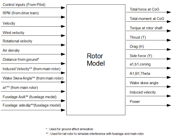
RTDynamics SDK provides two rotor models which are implemented in FGRotorBladeElementTheory and FGRotorMomentumTheory classes. These models simulate aerodynamic and mechanical behavior of a rotor. Both of the models are suitable as main and tail rotors, however, a good tradeoff between performance and fidelity is obtained when the blade element model is used for the main rotor and the momentum theory based model is used for the tail rotor. Inputs and outputs of the model are summarized below:
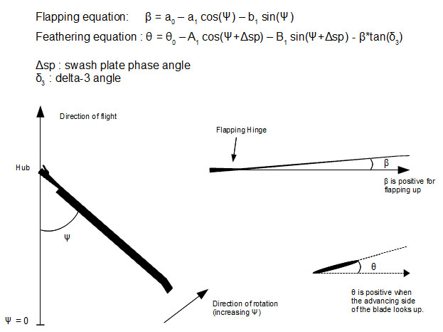
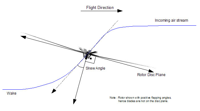
Following figure summarizes some of the conventions used in the models. The figure is prepared for a CCW rotor, but except the azimuth (psi) the definitions remain the same. Azimuth angle increases always in the direction of rotation and differs for CCW and CW rotors.
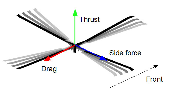
Rotor models compute forces (thrust, drag and side force) and moments (pitching, rolling and yawing) at the rotor hub and apply them to the aircraft at its center of gravity. The direction convention for forces and moments is independent of rotor rotation direction.
Rotor models compute induced velocity and rotor wake skew angle which are used by other simulation model components to simulate interference effects, e.g. downwash on fuselage. Induced velocity is positive downwards. Rotor wake skew angle is defined zero downwards and increases bacwards (see figure).
FGRotorBladeElementTheory configuration format
To configure a blade element theory model based rotor, a <Rotor> section with type FGRotorBladeElementTheory must be defined in the configuration file. Configuration parameters of the rotor must be in this section.
The layout of the configuration format is as follows.
<Rotor type="FGRotorBladeElementTheory">

	<Geometry>
		<Position x y z /> <!-- RTDynamics coordinate system ( Y forward, X rightward, Z up) relative to the vehicle body coordinate system. -->
		<Tilt lateralTilt longitudinalTilt /> <!-- degrees, positive values denote a right/back tilt -->
		<Blades radius chord count hingeOffset flappingHingeLowerLimit flappingHingeHigherLimit />
		<Rotation clockwise /> <!-- true/false -->
		<Delta3 angle /> <!-- pitch-flap coupling in degrees. see "blade azimuth, feathering and flapping diagram" -->
	</Geometry>

	<MechanicalFeatures Ir Ib maxBrakeTorque />
	<!-- Ir : Moment of inertia (rotational inertia) of the rotor about the shaft axis in kg*m^2. -->
	<!-- Ib : Moment of inertia (rotational inertia) of a blade about the flapping hinge in kg*m^2. -->
	<!-- maxBrakeTorque : Maximum torque that is applied by the rotor brake in N*m. -->

	<AerodynamicFeatures>

		<InducedVelocity thrustGain rollMomentGain pitchMomentGain groundEffectFactor />
		<!-- unitless, empirical correction factors, default 1 = no effect -->
		<!-- thrustFactor: strength of the induced velocity depending on the rotor thrust -->
		<!-- groundEffectFactor : strength of the ground effect -->

		<DesignRPM rpm /><!-- If no engine is connected to the rotor, it will rotate with this speed -->

		<Controls swashPlatePhaseAngle /> <!-- degrees, see "blade azimuth, feathering and flapping diagram" -->

		<Blades twist><!-- degrees, usually a negativ value -->

		<LiftCoefficient>

						Mach_1		Mach_2	...	Mach_m
			AoA_1		Cl_1_1		Cl_1_2	...	Cl_1_m
			AoA_2		Cl_2_1		Cl_2_2	...	Cl_2_m

			<!-- . . . -->

			AoA_n		Cl_n_1		Cl_n_2	...	Cl_n_m

		</LiftCoefficient>


		<DragCoefficient>

						Mach_1		Mach_2	...	Mach_m
			AoA_1		Cd_1_1		Cd_1_2	...	Cd_1_m
			AoA_2		Cd_2_1		Cd_2_2	...	Cd_2_m
			.
			.
			.
			AoA_n		Cd_n_1		Cd_n_2	...	Cd_n_m

		</DragCoefficient>

		<!-- 2D look up tables describe the lift and drag coefficients for various Mach number and angle of attack combinations. -->
		<!-- Lift and drag coefficients are unitless aerodynamic parameters. -->
		<!-- Mach numbers must start from zero and go until the largest expected maximum Mach number for the advancing blade's tip. -->
		<!-- Angle of attack range must be [-180,180] to ensure that the tables provide a look up value in all flight conditions. -->

		</Blades>

	</AerodynamicFeatures>

</Rotor>
FGRotorMomentumTheory configuration format
To configure a momentum theory model based rotor, a <Rotor> section with type FGRotorMomentumTheory must be defined in the configuration file. Configuration parameters of the rotor must be in this section.
A simplified layout of the model configuration is provided below.
<Rotor type="FGRotorMomentumTheory">
<Geometry>
	<Position x y z /><!-- RTDynamics coordinate system ( Y forward, X rightward, Z up) relative to the vehicle body coordinate system. -->
	<Tilt lateralTilt longitudinalTilt /> <!-- degrees, positive values denote a right/back tilt -->
	<Blades radius chord count hingeOffset flappingHingeLowerLimit flappingHingeHigherLimit />
	<Rotation clockwise /> <!-- true/false -->
	<Delta3 angle /> <!-- pitch-flap coupling in degrees. see "blade azimuth, feathering and flapping diagram" -->
</Geometry>

<MechanicalFeatures Ir Ib maxBrakeTorque />
<!-- Ir : Moment of inertia (rotational inertia) of the rotor about the shaft axis in kg*m^2. -->
<!-- Ib : Moment of inertia (rotational inertia) of a blade about the flapping hinge in kg*m^2. -->
<!-- maxBrakeTorque : Maximum torque that is applied by the rotor brake in N*m. -->

<AerodynamicFeatures>
	<Blades liftCurveSlope zeroLiftDragCoefficient twist />
	<!-- liftCurveSlope : unitless, Slope of the blade lift curve. X axis of the curve is assumed to be in degrees. -->
	<!-- Example: If a lift curve has Clmax = 1.5 at 15 degrees , liftCurveSlope will be 1.5/15 = 0.1. -->
	<!-- zeroLiftDragCoefficient : unitless, Drag coefficient of the blades at zero lift. -->
	<!-- twist : Blade twist in degrees. -->
	<Power inducedPowerCorrectionFactor /> <!-- an empirical correction factor for the computation of the induced power -->
	<GroundEffect magnitude /> <!-- unitless, empirical correction factor -->
	<DesignRPM rpm /> <!-- If no engine is connected to the rotor, it will rotate with this speed -->
</AerodynamicFeatures>
<MainRotor>
Fuselage
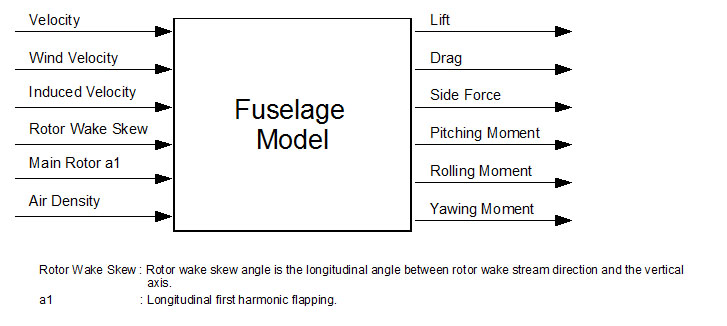
Fuselage model is implemented in FGHeliFuselage100 class. Inputs and outputs of the model are summarized in the following diagram:
All forces and moments are computed at the center of gravity.
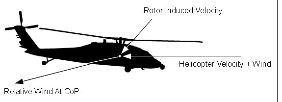
During simulation update, fuselage model initially computes the effective relative wind (in other words, air stream velocity) acting on the fuselage. To compute the effective relative wind helicopter velocity, wind velocity and the main rotor downwash is used. Downwash is characterized by rotor wake skew angle and induced velocity, which are outputs of the rotor model (see Rotor model section for details). Unfortunately, these values can not be used directly to compute the rotor's effect on the fuselage because they are only reference values and the actual induced velocity changes depending on the position on the helicopter. Different parts of the fuselage receive different amount of induced air stream. Therefore there are two curve sets in the configuration file ( MainRotorDownwash and MainRotorInplanewash) which define downwash and inplanewash coefficients depending on the rotor wake skew angle. Using induced velocity output of the main rotor and these curves (as look-up tables indexed by rotor wake angle) final air stream velocity vector is computed.
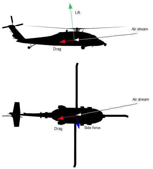
Both the magnitude and direction of the incoming air stream affect the resulting forces and moments so the angle of attack and side slip angles for the effective relative wind are computed. Configuration parameters of the fuselage includes two curves for each force and moment. One of them bases on angle of attack and the other on side slip angle. These are used as look-up tables for computing the forces and the moments.
FGHeliFuselage100 configuration format
Simplified layout of the model configuration is provided below.
<Fuselage CoPX CoPY CoPZ>
	<MainRotorInplanewash>
		<Low_a1 a1>
			WakeSkewAngle_1 Cinplanewash_1
			WakeSkewAngle_2 Cinplanewash_2
			.
			.
			.
			WakeSkewAngle_n Cinplanewash_n
		</Low_a1>

		<Medium_a1 a1>
			<!-- As in Low_a1 -->
		</Medium_a1>

		<High_a1 a1>
			<!-- As in Low_a1 -->
		</High_a1>
	</MainRotorInplanewash>

	<MainRotorDownwash>
		<Low_a1 a1>
			WakeSkewAngle_1 Cdownwash_1
			WakeSkewAngle_2 Cdownwash_2
			.
			.
			.
			WakeSkewAngle_n Cdownwash_n
		</Low_a1>

		<Medium_a1 a1>
			<!-- As in Low_a1 -->
		</Medium_a1>

		<High_a1 a1>
			<!-- As in Low_a1 -->
		</High_a1>
	</MainRotorDownwash>

	<LiftDueToAoA>
		AngleOfAttack_1		Cliftaoa_1
		AngleOfAttack_2		Cliftaoa_2
		.
		.
		.
		AngleOfAttack_n		Cliftaoa_n
	</LiftDueToAoA>

	<LiftDueToSideslip>
		SideSlip_1		Cliftsideslip_1
		SideSlip_2		Cliftsideslip_2
		.
		.
		.
		SideSlip_n		Cliftsideslip_n
	</LiftDueToSideslip>

	<SideForceDueToAoA>
		<!-- Similar to LiftDueToAoA -->
	</SideForceDueToAoA>

	<SideForceDueToSideslip>
		<!-- Similar to LiftDueToSideslip -->
	</SideForceDueToSideslip>

	<DragDueToAoA>
		<!-- Similar to LiftDueToAoA -->
	</DragDueToAoA>

	<DragDueToSideslip>
		<!-- Similar to LiftDueToSideslip -->
	</DragDueToSideslip>

	<PitchingMomentDueToAoA>
		<!-- Similar to LiftDueToAoA -->
	</PitchingMomentDueToAoA>

	<PitchingMomentDueToSideslip>
		<!-- Similar to LiftDueToSideslip -->
	</PitchingMomentDueToSideslip>

	<RollingMomentDueToAoA>
		<!-- Similar to LiftDueToAoA -->
	</RollingMomentDueToAoA>

	<RollingMomentDueToSideslip>
		<!-- Similar to LiftDueToSideslip -->
	</RollingMomentDueToSideslip>

	<YawingMomentDueToAoA>
		<!-- Similar to LiftDueToAoA -->
	</YawingMomentDueToAoA>

	<YawingMomentDueToSideslip>
		<!-- Similar to LiftDueToSideslip -->
	</YawingMomentDueToSideslip>
</Fuselage>
Fuselage
CoPX CoPY CoPZ: Position of center of pressure relative to the fuselage center of gravity. These parameters are in meters.
MainRotorDownwash and MainRotorInplanewash
Each of these sections contain three curves which define the relationship between the induced velocity acting on the fuselage and the induced velocity of the main rotor. MainRotorDownwash is used to compute Cdownwash and MainRotorInplanewash is used to compute Cinplanewash. These are used to compute the rotorwash acting on the fuselage as follows:
- Downwash (positive downwards) = Main Rotor Induced Velocity * Cdownwash
- Inplanewash (positive backwards) = Main Rotor Induced Velocity * Cinplanewash
MainRotorDownwash and MainRotorInplanewash can contain three curves for three different a1 (main rotor longitudinal flapping in degrees) values. Depending on current a1, two nearest curves are selected and the coefficients for the current wake skew angle are looked up. Final coefficient is found by linear interpolation between the look-up values.
Force curves (Lift, Drag and Side force due to angle of attack and side slip)
These curves contain lift, drag and side force coefficients depending on angle of attack and side slip. Coefficients due to angle of attack and side slip are found by using these curves as look-up tables. An example computation is provided below:
- Clift = Cliftaoa + Cliftsideslip
- Lift = dynamic pressure * Clift
Moment curves (Pitching, yawing and rolling moments due to angle of attack and side slip)
These curves contain pitching moment, yawing moment and rolling moment coefficients depending on angle of attack and side slip. Coefficients due to angle of attack and side slip are found by using these curves as look-up tables. An example computation is provided below:
- Cpitch = Cpitchaoa + Cpitchsideslip
- PitchingMoment = dynamics pressure * Cpitch
Stabilizers
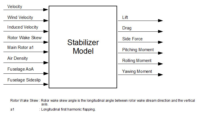
Stabilizers are simulated with FGHelicopterStabilizerWing class. It is derived from FGWing and inherits most of the functionality from it. It extends FGWing by adding downwash and dynamic pressure change effects.
FGHelicopterStabilizerWing configuration
GenHeli600 allows definition of one vertical and two horizontal stabilizers. The definitions of the stabilizers are made in <VerticalStabilizer>, <HorizontalStabilizerRight> and <HorizontalStabilizerLeft> sections in the configuration file. Simplified layout of the configuration is provided below.
<HorizontalStabilizerRight>
	<Geometry>
		<Position x y z /><!-- aerodynamic center of the wing with respect to the reference datum in meters -->
		<Up x y z /><!-- vector of the wing UP direction in vehicle body coordinates -->
		<Front x y z /><!-- vector of the wing FRONT direction in vehicle body coordinates -->
		<SurfaceArea area /><!-- m2 -->
	</Geometry>

	<AerodynamicFeatures>
		<DynamicPressureRatio>
			<AoA>
				AoA_1 ratio_1
				AoA_2 ratio_2
				.
				.
				.
				AoA_n ratio_n
			</AoA>

			<Sideslip>
				Sideslip_1 ratio_1
				Sideslip_2 ratio_2
				.
				.
				.
				Sideslip_n ratio_n
			</Sideslip>
		</DynamicPressureRatio>

		<MainRotorDownwash>
			<Low_a1 a1>
				WakeSkew_1 DownwashFactor1
				WakeSkew_2 DownwashFactor2
				.
				.
				.
				WakeSkew_n DownwashFactorn
			</Low_a1>

			<Medium_a1 a1>
				WakeSkew_1 DownwashFactor_1
				WakeSkew_2 DownwashFactor_2
				.
				.
				.
				WakeSkew_n DownwashFactor_n
			</Medium_a1>

			<High_a1 a1>
				WakeSkew_1 DownwashFactor_1
				WakeSkew_2 DownwashFactor_2
				.
				.
				.
				WakeSkew_n DownwashFactor_n
			</High_a1>
		</MainRotorDownwash>

		<MainRotorInplanewash>
			<!-- As in MainRotorDownwash -->
		</MainRotorInplanewash>

		<LiftCurve>
			AoA_1 Cl_1
			AoA_2 Cl_2
			.
			.
			.
			AoA_n Cl_n
		</LiftCurve>

		<DragCurve >
			AoA_1 Cd_1
			AoA_2 Cd_2
			.
			.
			.
			AoA_n Cd_n
		</DragCurve>
	</AerodynamicFeatures>
<HorizontalStabilizerRight>
DynamicPressureRatio
It is possible that due to interference with the fuselage, dynamic pressure observed at the stabilizers are different than the one which is computed using air density and the velocity. This effect is simulated using curves which contain the dynamic pressure ratio vs. fuselage angle of attack and side slip angles. Following equation is used:
Stabilizer Dynamic Pressure = Dynamic Pressure * RatioAoA * RatioSideslip
Here RatioAoA is looked up from <AoA> section (angles in degrees, ratio unitless), and RatioSideslip from <sideslip> (angles in degrees, ratio unitless) sections.
MainRotorDownwash and MainRotorInplanewash
Each of these sections contain three curves which define the relationship between the induced velocity acting on the stabilizer and the induced velocity of the main rotor. MainRotorDownwash is used to compute Cdownwash and MainRotorInplanewash is used to compute Cinplanewash. These are used to compute the rotorwash acting on the stabilizer as follows:
Downwash (positive downwards) = Main Rotor Induced Velocity * Cdownwash
Inplanewash (positive backwards) = Main Rotor Induced Velocity * Cinplanewash
MainRotorDownwash and MainRotorInplanewash can contain three curves for three different a1 (main rotor longitudinal flapping in degrees) values. Depending on current a1, two nearest curves are selected and the coefficients for the current wake skew angle are looked up. Final coefficient is found by linear interpolation between the look-up values.
LiftCurve and DragCurve
These curves contain the coefficient of lift and drag vs. angle of attack. Coefficients are unitless and angle of attack is in degrees.
Engine and Drive Train
RotorLib FDM has an extensible engine model architecture. Engine models are classes that are derived from RTD::EngineModelBase. An existing or user-developed engine model can be attached to the helicopter by defining it in the XML configuration file. To create an engine, an <Engine> section should be defined and engine type has to be set. The configuration parameters of the engine should be between opening and closing tags of the section. Here is an example which creates and configures a ConstantRPMEngine.
<Engine type="ConstantRPMEngine">
	<Performance maxPower="3000" />
	<ControllerParams P="0.04" I="1.0" D="0.0" offset="200" targetRPM="20900" />
</Engine>
Following figure provides an overview of RotorLib's engine and transmission model. The central component of the model is the transmission which receives the torques as input and computes the final RPM's of the rotors and the engine shaft. The resistance torques applied by the rotors to the transmission are the torques generated by the air resistance on the rotor blades. The engine torque shown in the figure is the torque produced by the engine to rotate the rotors. Transmission uses these torques and the information about rotor gear ratios and rotor rotational inertias to compute angular accelerations and finally the final RPM's for the current frame.
It is important to note that the engine does not update its own RPM. Engines and rotors provide only the torques acting on the system. Angular accelerations and hence the final RPM's are computed by the transmission model by solving an equation system where solutions for all variables are found simultaneously.
ConstantRPMEngine
ConstantRPMEngine engine model has an internal PID controller that tries to maintain the rotor RPM at a given rate. The input of the controller is RPM error ( targetRPM - currentShaftRPM ) and its output is shaft torque. The torque that is requested by the controller is not directly applied to the shaft. Final torque output is computed as follows:
Pmax = emergencyPower * (airDensity / 1.22406) * HP_to_Watt
Tmax = min( maxTorque , Pmax / (currentShaftRPM * RPM_to_radsec) )
Toutput = min( Tcontroller - currentShaftRPM2 * rotationResistance , Tmax )
Configuration format of the model is as follows:
<Engine type="ConstantRPMEngine">
	<General inertia throttleAlwaysFull />
	<Performance emergencyPower takeOffPower maximumContinuousPower maxTorque rotationResistance />
	<ControllerParams P I D offset targetRPM />
<Engine>
- inertia : Rotational inertia of the engine in kg*m2.
- throttleAlwaysFull : When set to true, which is the default, throttle input is ignored and always 100% throttle is assumed.
- maximumContinuousPower , takeOffPower , emergencyPower : Available engine power for maximum continuous and takeoff ratings in HP. These parameters are not used in the mathematical model but only as reference. TKOH engine has torque limits and damage defined in *.cpp config files.
- maxTorque : Maximum torque the engine can apply to the shaft. This parameter must be defined in N*m.
- rotationResistance : Engines have a small resistance to the rotation of the shaft due to internal friction. This resistance reduces the efficiency of the engines. In ConstantRPMengine, resistance is modeled as a torque that is proportional to the square of the RPM. rotationResistance parameter is used to adjust the strength of the resistance and has the unit N.m/ RPM2.
- A PID controller is used to regulate the engine torque output.
- output = P * error + clamp( I * errorIntegral , integralLimitLow , integralLimitHigh ) + D * errorDerivative + offset
- P, I, D, offset, integralLimitLow and integralLimitHigh are the configuration parameters. error is the input of the PID (in this case the RPM error). errorIntegral and errorDerivative are automatically computed. output is the torque, in N*m, that will be applied to the output shaft.
Control Systems
RTDynamics SDK has an extensible control system architecture. Existing and/or user developed control system components can be attached to the vehicles and configured using XML configuration files. Control system components are created and configured in <ControlSystem> section of the configuration file. In this section, for each component ( in other words, for each stage ) a <CSComponent> subsection must be defined and the component type must be set using the type attribute. Following example defines a single stage of type FCSRotationDamper
<ControlSystem>
	<CSComponent type="FCSRotationDamper">
		<YawController P="2" D="0" />
		<PitchController P="2.0" D="0" />
		<RollController P="2" D="0.2" />
	</CSComponent>
</ControlSystem>
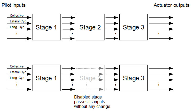
If multiple components are defined in the configuration, they are connected to each other in a cascade, i.e. each stage receives its inputs from the previous stage. Only the first stage receives its inputs directly from the application. A disabled stage passes its inputs to the next stage without any change. By enabling/disabling the stages, different automatic control system configurations can be obtained.
Each stage is a control system component. Input and output of each stage is of type RTD::InoutData
Control system components are not limited to operate only on their inputs and outputs. RTD::InputData is only the default input/output format. The information flow to and from a stage can be extended in two ways:
- Control system components can read from and write to all simulation variables of a vehicle. E.g. GenericControlSystem component works this way.
- Components can call each other's class methods to implement master/slave relationships. E.g. RotorLib FDM autopilot implementation works this way.
RTD::GenericControlSystem
GenericControlSystem component uses Generic Mathematical Model module.
MathExpression
A MathExpression operation contains multiple mathematical expressions separated with comma. These mathematical expressions are compiled into a byte code and can be computed very fast in run-time.
Mathematical expressions consist of standard algebraic operators, parantheses, a conditional operator, a predefined set of functions and the assignment operator ( "=" ). The aliases that are defined in the Variables section can be used to refer to simulation variables in the expressions. More information about the syntax and available functions is provided in the MathExpression Syntax Appendix.
In the following example average engine RPM and pitch rate in deg/sec are computed. The results are written to two newly created simulation variables.
<Variables>
	<Variable alias="rpm0" name="Engine_0/rpm" />
	<Variable alias="rpm1" name="Engine_1/rpm" />
	<Variable alias="pitchRateRadSec" member="X" name="angularVelocityBCS" />
	<Variable alias="pitchRateDegSec" dataType="REAL" name="pitchRateDegSec" />
	<Variable alias="averageRPM" dataType="REAL" name="averageRPM" />
</Variables>

<MathExpression>
	<Expression>
		averageRPM = (rpm0+rpm1)/2.0,
		pitchRateDegSec = pitchRateRadSec * 180.0 / 3.1415
	</Expression>
</MathExpression>
The first three variable declerations refer to existing simulation variables that are created when the vehicle is created and initialized. The next two, pitchRateDegSec and averageRPM , are created by the generic model. We compute new values and assign to these variables in the Expression section.
RTD::FCSRotationDamper
This control system component is used to dampen the rotational motion of the helicopter in all three axes. It can be used for both airplane and helicopters. FCSRotationDamper contains, for each rotational degree of freedom, a PD controller.
<FCSComponent type="FCSRotationDamper">
	<YawController P D />
	<PitchController P D />
	<RollController P D />
</FCSComponent>
YawController
Configures the PD controller that damps yawing motion.
P : Proportional coefficient of the controller.
D : Derivative coefficient of the controller.
PitchController
Configures the PD controller that damps pitching motion.
P : Proportional coefficient of the controller.
D : Derivative coefficient of the controller.
RollController
Configures the PD controller that damps rolling motion.
P : Proportional coefficient of the controller.
D : Derivative coefficient of the controller.
More info about PID controller concept on Wikipedia: http://en.wikipedia.org/wiki/PID_controller
Helicopter Control System Modeling
Helicopter flight control is accomplished by controlling the rotor swash plates, which, by axial movements or tilting, can change the blade pitch collectively (same amount of pitch at every blade azimuth) or cyclically (periodically changing amounts of pitch depending on current azimuth of the blade). Aerodynamic effects, that are produced by blade pitch control, can be used to control the thrust and rotational moments that are produced by a rotor.
Pilots control the swash plates, and hence the helicopters, with cyclic stick, collective lever and anti-torque pedals. Flight control system modeling is about modeling the way these control devices are connected to the swash plates. Every helicopter has a different mechanical mixing method, different actuators, and different stability augmentation methods. Because of this, GenHeli600 does not connect pilot inputs to the swash plates automatically. Instead, GenericControlSystem component must be used to connect control system outputs to the swash plates.
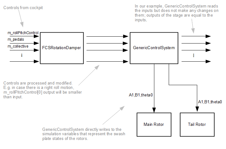
In the following example a simple flight control system is modeled. The first control system stage, which receives the pilot inputs, is a FCSRotationDamper. FCSRotationDamper modifies the inputs to reduce the angular rates. For example, if the helicopter has a positive roll rate (rolling right), FCSRotationDamper will reduce the RTD::PilotInputs::m_rollPitchControl[0] slightly to dampen this roll motion. The output of the stage will include the reduced value.
The second stage of the control system is a GenericControlSystem. Input to this component is the output of the first stage. In this stage, m_rollPitchControl input is used to tilt the main rotor swash plate and hence the rotor itself to produce pitching and rolling moments. m_collective is used to move the main rotor swash plate vertically for controlling the rotor thrust. Finally, m_pedals input is used to move the tail rotor swash plate axially to provide tail rotor thrust control (i.e yaw control).
Note In reality, most of the helicopters have a more complex mechanical mixer unit. For example, collective lever is usually connected to the tail rotor so that when collective lever is moved, some amount of yaw moment compensation is provided automatically. There are various similar mixing methods that are used to alleviate control coupling problems.
We have to change the simulation variables that represent swash plate state to connect the control inputs to the swash plates as described above. These variables are listed below. Note that, all variables are in radians :
- MainRotor/theta0 : Main rotor collective pitch.
- MainRotor/A1 : Main rotor cyclic blade pitch lateral component
- MainRotor/B1: Main rotor cyclic blade pitch longitudinal component
- TailRotor/theta0 : Tail rotor collective pitch
- TailRotor/A1 : Tail rotor cyclic blade pitch lateral component
- TailRotor/B1: Tail rotor cyclic blade pitch longitudinal component
In the example control system, following control ranges are used:
- Collective [6.5, 20] deg
- Lateral cyclic [-13 , 9] deg
- Longitudinal cyclic [-12 , 16] deg
- Pedals [30,-30] deg
You can find the configuration of the described system below. Note that, latCyclic , lonCyclic and pedals are in [-1,1] range. This is why they are mapped into [0,1] range inside the linearInterp function.
<ControlSystem>
	<FCSComponent type="FCSRotationDamper">
		<YawController P="2" D="0" />
		<PitchController P="2.0" D="0" />
		<RollController P="0.4" D="0.01" />
	</FCSComponent>

	<CSComponent type="GenericControlSystem">
		<Variables>
			<Variable name="CSComponent_1/ControlOutput/pitchRollControl" member="roll" alias="latCyclic" />
			<Variable name="CSComponent_1/ControlOutput/pitchRollControl" member="pitch" alias="lonCyclic" />
			<Variable name="CSComponent_1/ControlOutput/pedals" alias="pedals" />
			<Variable name="CSComponent_1/ControlOutput/collective" alias="collective" />

			<Variable name="MainRotor/A1" alias="A1m" />
			<Variable name="MainRotor/B1" alias="B1m" />
			<Variable name="MainRotor/theta0" alias="Th0m" />

			<Variable name="TailRotor/A1" alias="A1t" />
			<Variable name="TailRotor/B1" alias="B1t" />
			<Variable name="TailRotor/theta0" alias="Th0t" />
		</Variables>

		<MathExpression>
			<Expression>
				A1m = linearInterp( -13 , 9 , (latCyclic + 1)/2 ),
				B1m = linearInterp( -12 , 16 , (lonCyclic + 1)/2 ),
				Th0m= collective * 13.5 + 6.5,

				A1t = 0.0,
				B1t = 0.0,
				Th0t = linearInterp( 30 , -30 , (pedals + 1)/2 ),

				A1m = degToRad(A1m),
				B1m = degToRad(B1m),
				Th0m = degToRad(Th0m),
				Th0t = degToRad(Th0t)
			</Expression>
		</MathExpression>
	</CSComponent>
</ControlSystem>
RotorLibFDM::FCSHelicopterAutoTrim
This control system component is used to trim the helicopter automatically and hence remove the coupling between controls (i.e. collective / pedal coupling). It translates pilot inputs to requested heading, pitch and roll rates or to requested side slip and controls the actuators to achieve the desired state. The final result is a simpler flight.
FCSHelicopterAutoTrim is suitable for simulators where simple input devices, such as a joystick, is used. In case real helicopter input devices with trim lock controls are used, FCSHelicopterAutoTrim should not be used.
<FCSComponent type="FCSHelicopterAutoTrim">
	<YawRateAndSideslipController printDebugInfo>
		<YawRatePID  P I D offset integralMin integralMax />
		<SideslipPID P I D offset integralMin integralMax />
		<Transition speedLow speedHigh />
		<Maximums maxYawRate maxSideslip />
		<InputMapping nonlinearity />
	</YawRateAndSideslipController>
	<PitchRateController printDebugInfo>
		<PID P I D offset integralMin integralMax />
		<MaxPitchRate maxPitchRate />
	</PitchRateController>
	<RollRateController printDebugInfo>
		<PID P I D offset integralMin integralMax />
		<MaxRollRate maxRollRate />
	</RollRateController>
</FCSComponent>
YawRateAndSideslipController
This controller controls the pedals to reach and maintain a certain yaw rate or side slip. Yaw rate control mode is active at low speeds, whereas side slip control mode is activated at high speeds. The mode change occurs smoothly within a user defined speed range (see Transition below). Within this transition region, both yaw rate and side slip control modes are active but their contribution to the final output varies depending on speed.
printDebugInfo : A boolean parameter (possible values "true" and "false" ) to enable/disable debug output to the console from the controller. This is useful for the parametrization of the controller.
YawratePID: Parameters of the PID controller that is used to control yaw rate. Error input to this PID is desired yaw rate - current yaw rate. Desired yaw rate is determined by the pedal input, i.e. pilot's pedal input is translated to a desired yaw rate by the controller.
P : Proportional coefficient of the controller.
I : Integral coefficient of the controller.
D : Derivative coefficient of the controller.
offset : "Zero point" of the controller. When error, error derivative and error sum is zero resulting value will be offset.
IntegralMin and integralMax : Minimum/Maximum value the error sum can reach. If the sum of errors go below/above this value it is clamped to this value.
SideslipPID: Parameters of the PID controller that is used to control side slip. Error input to this PID is desired side slip - current side slip. Desired side slip is determined by the pedal input, i.e. pilot's pedal input is translated to a desired side slip by the controller.
P : Proportional coefficient of the controller.
I : Integral coefficient of the controller.
D : Derivative coefficient of the controller.
offset : "Zero point" of the controller. When error, error derivative and error sum is zero resulting value will be offset.
IntegralMin and integralMax : Minimum/Maximum value the error sum can reach. If the sum of errors go below/above this value it is clamped to this value.
Transition
YawRateAndSideslipController is designed so that it interprets the pilot pedal input as desired yaw rate at low speeds and as desired side slip at high speeds. A transition region based on speed can be defined to enable a smooth transition between these modes.
speedLow and speedHigh : Below speedLow, the pedal input will be interpreted as desired yaw rate and after speedHigh as desired side slip. Between these two speeds, the outputs of the Yaw Rate and Side slip subcontrollers will be linearly mixed.
Maximums
maxYawRate : Maximum yaw rate that can be requested from the controller. This parameter is in deg/s and must be positive always.
maxSideslip : Maximum side slip angle that can be requested from the controller. This parameter is in degrees and must be positive always.
InputMapping
nonlinearity : In some cases, it might be better to pass the pilot input to the control system non-linearly. For example, in a desktop simulator, where the input device is a common joystick, we might want to have a better precision at the zero point. We can define an exponential relationship between pilot's input and the control system input using nonlinearity parameter. The pedal input that is given to the control system is computed as follows: pedal input to controller = (|pilot pedal input| ^ nonlinearity) * sign(pilot pedal input).
PitchRateController, RollRateController
Controllers for pitch and roll rates.
printDebugInfo : A boolean parameter (possible values "true" and "false" ) to enable/disable debug output to the console from the controller. This is useful for the parametrization of the controller.
PID : Parameters of the PID controller that is used to regulate the rotational motion.
P : Proportional coefficient of the controller.
I : Integral coefficient of the controller.
D : Derivative coefficient of the controller.
offset : "Zero point" of the controller. When error, error derivative and error sum is zero resulting value will be offset.
IntegralMin and integralMax : Minimum/Maximum value the error sum can reach. If the sum of errors go below/above this value it is clamped to this value.
MaxPitchRate and MaxRollRate
These are maximum angular speeds the controllers are trying to reach. E.g. if control stick is pulled 100% right, RollRateController will try to reach a roll rate of maxRollRate. The values are in deg/sec.
InputMapping
nonlinearity : In some cases, it might be better to pass the pilot input to the control system non-linearly. For example, in a desktop simulator, where the input device is a common joystick, we might want to have a better precision at the zero point. We can define an exponential relationship between pilot's input and the control system input using nonlinearity parameter. The actual input that is given to the control system is computed as follows: input to controller = (|pilot input| ^ nonlinearity) * sign(pilot input).
Ground contacts
Interaction with terrain is simulated by ground contacts, classes that are derived from RTD::FGGroundContactBase. Highest fidelity ground contact implementation is RTD::FGGroundContact200 class in the current version. Initially gears are extended.
Ground contacts are defined in <GroundContacts> section of the configuration file. Each new ground contact has to be defined in its own section with name <GroundContact>. Also the type of the ground contact has to be declared here using the type attribute. In <GroundContacts> section <GeneralConfiguration> subsection is used to define some parameters that are common to all ground contacts.
<GroundContacts>
	<GeneralConfiguration
		gearExtensionTime gearDragCoefficient
		gearReferenceArea maxSteerableGearDeflection
		steerableGearSpeedCorrectionFactor />
		<GroundContact type>
		<!-- Parameters Related to chosen ground contact model -->
	</GroundContact>
</GroundContacts>
GeneralConfiguration
- gearExtensionTime: Time needed to extend/retract landing gears in seconds.
- gearDragCoefficient: Coefficient of drag for landing gears.
- gearReferenceArea: Reference area of the landing gears to be used in air drag computation.
- maxSteerableGearDeflection: Maximum deflection (in degrees) of the steerable gears.
- steerableGearSpeedCorrectionFactor: As the speed of the aircraft increases, deflections of steerable gears are automatically reduced to keep the aircraft controllable. This parameter defines the strength of this correction.
GroundContact
A multitude of <GroundContact> </GroundContact> sections can be defined. The type parameter defines which ground contact model (E.g. FGGroundContact200) has to be used. Inside the opening and closing tags, configuration parameters of the chosen model has to be provided.
FGGroundContact200 configuration
FGGroundContact200 implements a multibody dynamics based ground contact model. It supports inclined and moving surfaces (e.g. for ship deck landing).
<GroundContact type="FGGroundContact200">
	<Features isBrakable isRetractable isSteerable />
	<Suspension>
		<MountStation x y z />
		<SliderAxis x y z />
		<SuspensionLength length />
		<SpringParameters
			springConstant
			damperConstant
			maxCompression />
	</Suspension>
	<Wheel mass radius>
		<RollAxis x y z />
		<Friction
			slidingFriction
			resistanceTorqueNoBrake
			resistanceTorqueFullBrake />
	</Wheel>
	<SteeringController
		maxTorque
		maxRotSpeed
		controllerGain
		inverseRotation
		keepCenter />
	<Damage thresholdLoad />
</GroundContact>
Features
General features of the ground contact.
- isBrakable: Is the ground contact a brakable landing gear? (true or false)
- isRetractable: Is the ground contact a retractable landing gear? (true or false)
- isSteerable: Is the ground contact a steerable landing gear? (true or false)
Suspension
Parameters of the suspension.
- MountStation: Position at which the landing gear is mounted onto the aircraft body. Relative to center of gravity and in meters.
- SliderAxis: This is a unit direction vector which determines along which direction suspension slider can move. It is defined relative to aircraft body coordinates in RTDDynamics coordinate system convention.
- SuspensionLength: Length of the suspension, i.e. the distance from mount station to middle point of wheel when suspensions are not compressed or decompressed. In meters.
- SpringParameters
- springConstant: Spring constant of the suspension spring. In N/m.
- damperConstant: Damper constant of the suspension spring. In N*sec/meter.
- maxCompression: Maximum amount the suspension spring can be compressed. This value should be less than or equal to suspension length. In meters.
Wheel
Parameters of the wheel.
- mass: Mass in Kg.
- radius: Radius of the wheel in meters.
- rotationalInertia: Rotational inertia of the wheel in Kg*m^2.
- RollAxis: A direction vector that defines the axis of wheel rotation. It is defined relative to aircraft body coordinates.
- Friction
- slidingFriction: Coefficient of friction between the tire and the ground.
- resistanceTorqueNoBrake and resistanceTorqueFullBrake: An effective resistance torque from linear interpolation of resistanceTorqueNoBrake and resistanceTorqueFullBrake depending on the amount of applied wheel brake is applied to the wheel continuously to simulate rolling friction. The resistance torque acts in a direction that opposes the current rotation of the wheel. In N*m.
SteeringController
- maxTorque: The steering controller rotates the wheel left or right depending on the pilot's input for steering on the ground. This parameter defines how much torque can be applied to the wheel for this purpose. This parameter is in N*m.
- maxRotSpeed: This parameter defines how fast the wheel can rotate around the vertical axis. In Deg/sec.
- controllerGain: The torque applied to the wheel to rotate it is proportional to the difference of pilot's desired wheel direction and current direction multiplied by \e m_steeringControllerGain (the result is clamped at \e m_steeringMaxTorque ). This parameter is unitless.
- inverseRotation: If this parameter is set to true, the wheel will rotate in the opposite direction of the pilot input (if pilot input is to the right wheel will rotate to the left etc. ). This is necessary if the steering wheel is at the back instead of front.
- keepCenter: If this parameter is set to true, the wheel will not be affected by the pilot's control input but instead will try to keep the wheel in center always. This is useful to model free rotating wheels (a wheel that can rotate around vertical axis but is not actively controlled by actuators ).
Damage
- thresholdLoad: During landing the forces acting on the wheel are transferred to the fuselage. Beyond a certain threshold the transferred forces result in damage in the aircraft. The load defined in thresholdLoad (in N) is the threshold used for this purpose.

